Bipolar transistors
6.
6.1. Device, constructive – technological features, circuit of insert
The bipolar transistor terms a three-electrode semiconductor device with two or more interacting electron-hole junction. In the transistor alternate as an electrical conductivity three regions of a semi-conductor, for what in a homogeneous semi-insulating substrate of silicon Si-i the methods of epiplanar technique shape regions of a collector, basis and emitter, (fig. 6.1). For it in a plate Si-n, employee by a collector, the method of a local diffusion (introduction of atoms of doping substance in a chip of a semi-conductor through some part of its surface) forms base region (Si-p). In this region also method of a local diffusion forms emitter region (Si-n) with high density of a donor dopant. On boundary region of emitter with base, and also on boundary of base region with collector are formed two electron-hole (p-n) junctions - emitter and collector (on a title of extreme regions of transistor structure).
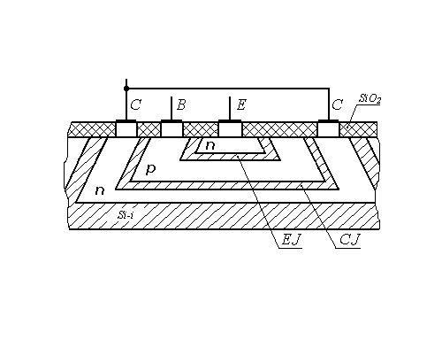
Fig. 6.1. Planar n-p-n structure of the bipolar transistor
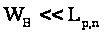
The
junctions appear interacting, if distance between them, called in
breadth of basis
 ,
is smaller diffusion lengths of mobile carriers of a charge. The
diffusion length
 is a distance, which transits an electron and vacant electron site
from a moment of occurrence in a semi-conductor up to a moment of a
recombination
 .
The area of collector junction always is more than the area of emitter junction. The region of the emitter should have higher electrical conductivity, than basis and collector. An impurity concentration in the region of the transistor owe corresponds as:
 .
(6.1)
Depending on the order of alternation of regions as an electrical conductivity distinguish structures p-n-p and n-p-n of types.
In a fig. 6.2 the structures p-n-p and n-p-n and their legend on circuitries are shown.
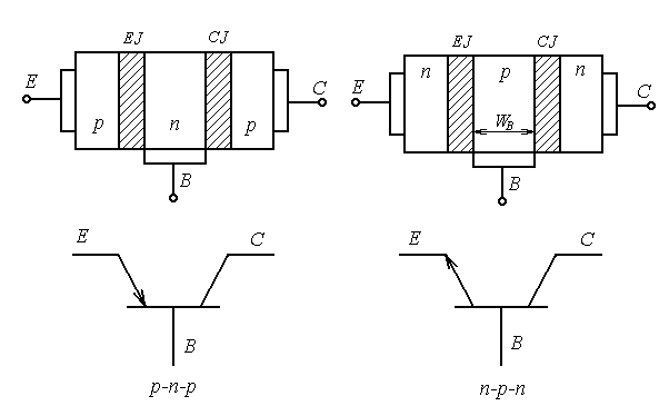
Fig. 6.2. Flat one-dimensional model BT and legends
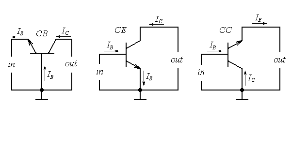
Fig. 6.3. The circuits of insert of bipolar transistors
As a device of an electric circuit, transistor use by such fashion, that one of its electrodes is entering, and another-output. The third electrode is common concerning an input and exit. Depending on what electrode is common, distinguish three circuits of insert of the transistor: common-base (CB), common emitter (CE) and common collector (CC) (fig. 6.3).
6.2. Conditions of insert of the transistor. Static parameters.
Physical processes
By operation of the transistor the voltages from exterior power supplys are affixed to its electrodes. Depending on polarity voltages affixed to electrodes, each of p-n-junctions the transistor can be switched on in direct or in the opposite direction. Four conditions of insert of the transistor are possible.
The table 6.1
|
Title of junction |
Insert of junction |
A title of a condition of insert of the transistor |
|
EJ CJ |
Backward Backward |
Condition a splitting contact |
|
EJ CJ |
Direct Direct |
Condition of saturation |
|
EJ CJ |
Direct Backward |
Fissile condition |
|
EJ CJ |
Backward Direct |
Inverse condition |
1. Condition a splitting contact. In a condition a splitting contact both p-n- junction are backswitched on (high-ohmic state of a section E-C). In electrodes of the transistor the thermal currents backswitched of junctions flow past which are static parameters of a condition the splitting contact. In each of three circuits of insert of the transistor these parameters have particular magnitudes. Their labels look like
for
the circuit with CB -
 ;
for
the circuit with CE -
 ;
for
the circuit with CC -
 ,
where the first index means an electrode, in which the current flows past;
the second index – circuit of insert;
the third index - requirement in the rest of the circuit:
о - absence of a current in the other electrode - no-load operation,
s - short-circuit in the rest of the circuit.
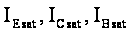
2. Condition of saturation. In a condition of saturation both p-n-junctions are directly switched on, the junctions saturated with mobile carriers of a charge, their resistances are small. The section E-C has high conductance and it is possible to consider it short-circuited.
Static parameters
are the saturation currents in electrodes the transistor
 and residual voltages
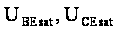 .
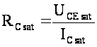
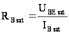
A voltage ratio and currents relevant electrodes give magnitudes of
resistances of saturation:
 ;
 .
3. Fissile condition. In a fig. 6.4 the flat one-dimensional model of the transistor is shown, which emitter junction is switched on in a forward direction, and collector junction - in backward. Such insert corresponds to a fissile condition, and the transistor has intensifying properties. The principle of operation of the transistor in a fissile condition grounded on use of the following phenomena:
- injection of majority carriers through emitter junction;
- transport of injected carriers through basis owing to diffusions and drift;
- recombination of nonequilibrium carriers in basis;
- extractions of carriers from basis in a collector by a region of collector junction.
The injection of
carriers stipulates transiting through emitter p-n-junction of
diffusive currents: hole
 and electronic
 .
In an external circuit of emitter the current of injection flows past
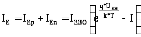 ,
(6.2)
where
- hole current of injection of the emitter;
- electronic current
of injection of the emitter.
For transistor
structure p-n-p of a type the relation between admixtures in the
emitter and basis is defined, as: .
Therefore
 .
The relation between component of an emitter current is evaluated coefficient of injection
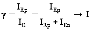 (6.3)
The injection of carriers from the emitter in basis rises density
minority carriers in basis. Their density on boundary of emitter junction for p-n-p of structure is defined by a relation
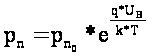 (6.4)
Appeared near to
emitter junction in basis a charge of vacant electron sites almost
instantaneous, during a dielectric relaxation
 seconds, is cancelled by a charge of electrons affluent in basis from
a radiant
 .
Circuit of a current the emitter - basis appears made and ensures
course of an emitter current. Magnification near to emitter junction
the electron concentrations and vacant electron sites are established
by a lapse rate of densities nonequilibrium carriers in basis
 and
 .
Under an operation of lapse rates
densities there is a diffusive driving of nonequilibrium vacant
electron sites and electrons through basis from the emitter to a
collector.
Diffusion of
vacant electron sites in basis is attended their recombination with
by electrons. On place of recombined electrons in basis from the
external circuits of a radiant
act other electrons, establishing together with electrons leaving
basis in the emitter, base current recombinations
 .
As breadth of basis is much less diffusion lengths of carriers
,
a loss of carriers in basis at the expense of recombination is
inappreciable, and current of a recombination
on one, two order are less than a current
 .
The vacant
electron sites injected by the emitter in basis and which have
reached collector backswitched junction, get in its accelerating
region and are thrown in region of a collector. The collector current
 is established:
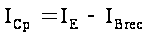 .
Process of
transport of minority nonequilibrium carriers through basis is
evaluated by a transport coefficient
 .
Coefficient
of transport depends from breadth of
basis
and diffusion length of vacant electron sites
 :
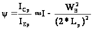 (6.5)
Than more vacant
electron sites is injected by the emitter in basis, than more them
extract a collector, augmenting a collector current. Therefore
current
 is proportional to an emitter current and is termed current
controlled of a collector, which in view of relations (6.3) and (6.5)
is defined by a relation (6.6) also records as follows:
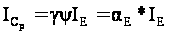 (6.6)
 - is termed as an
integrated (static) transmission factor current of emitter in a
collector circuit and in view of relations (6.3), (6,5) is defined by
the following formula:
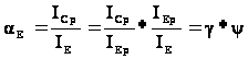 .