Airfoils and Lift
As the AOA of the wing section is increased, the point of minimum pressure moves towards the leading edge, with increasingly high suction being achieved. This means that the pressure then has to rise by a greater extent downstream of the minimum pressure point and that the length of wing surface exposed to the rising pressure is increased. The resulting adverse pressure gradient becomes more severe as AOA is increased. This has serious implications for the boundary layer, which is always likely to separate from the wing surface under such conditions.
The Swept Wing
The whole idea of sweeping an aircraft's wing is to delay the drag rise caused by the formation of shock waves. The swept-wing concept had been appreciated by German aerodynamicists since the mid-1930s, and by 1942 a considerable amount of research had gone into it. However, in the United States and Great Britain, the concept of the swept wing remained virtually unknown until the end of the war. Due to the early research in this area, this allowed Germany to successfully introduce the swept wing in the jet fighter Messerschmitt ME-262 as early as 1941.
Early British and American jet aircraft were therefore of conventional straight-wing design, with a high-speed performance that was consequently limited. Such aircraft included the UKGloster Meteor F.4 , the U.S. Lockheed F-80 Sooting Star and the experimental U.S. jet, the Bell XP-59A Airacomet.
After the war German advanced aeronautical research data became available to the United States Army Air Force (USAAF) as well as Great Britain. This technology was then incorporated into their aircraft designs. Some early jets that took advantage of this technology were the North American F-86 Sabre, the Hawker Hunter F.4 and the Supermarine Swift FR.5.
Not to be outdone, the Soviet Union introduced the swept wing in the Mikoyan Mig-15 in 1947. This aircraft was the great rival of the North American F-86 Sabre during the Korean War.
Jet Engine Theory
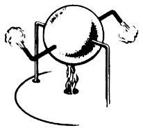
Centuries ago in 100 A.D., Hero, a Greek philosopher and mathematician, demonstrated jet power in a machine called an "aeolipile." A heated, water filled steel ball with nozzles spun as steam escaped.
Over the course of the past half a century, jet-powered flight has vastly changed the way we all live. However, the basic principle of jet propulsion is neither new nor complicated.
Centuries ago in 100 A.D., Hero, a Greek philosopher and mathematician, demonstrated jet power in a machine called an "aeolipile." A heated, water filled steel ball with nozzles spun as steam escaped. Why? The principle behind this phenomenon was not fully understood until 1690 A.D. when Sir Isaac Newton in England formulated the principle of Hero's jet propulsion "aeolipile" in scientific terms. His Third Law of Motion stated: "Every action produces a reaction... equal in force and opposite in direction."
The jet engine of today operates according to this same basic principle. Jet engines contain three common components: the compressor, the combustor, and the turbine. To this basic engine, other components may be added, including:
A nozzle to recover and direct the gas energy and possibly divert the thrust for vertical takeoff and landing as well as changing direction of aircraft flight.
An afterburneror augmentor, a long "tailpipe" behind the turbine into which additional fuel is sprayed and burned to provide additional thrust.
A thrust reverser, which blocks the gas rushing toward the rear of the engine, thus forcing the gases forward to provide additional braking of aircraft.
A fan in front of the compressor to increase thrust and reduce fuel consumption.
An additional turbine that can be utilized to drive a propeller or helicopter rotor.
The Turbojet Engine
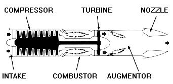
A turbojet engine.
The turbojet is the basic engine of the jet age. Air is drawn into the engine through the front intake. The compressor squeezes the air to many times normal atmospheric pressure and forces it into the combustor. Here, fuel is sprayed into the compressed air, is ignited and burned continuously like a blowtorch. The burning gases expand rapidly rearward and pass through the turbine. The turbine extracts energy from the expanding gases to drive the compressor, which intakes more air. After leaving the turbine, the hot gases exit at the rear of the engine, giving the aircraft its forward push... action, reaction !
For additional thrust or power, an afterburner or augmentor can be added. Additional fuel is introduced into the hot exhaust and burned with a resultant increase of up to 50 percent in engine thrust by way of even higher velocity and more push.
The Turboprop/Turboshaft Engine
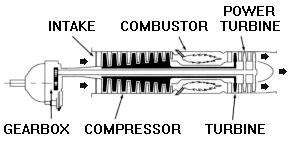
A turboprop, or turboshaft engine.
A turboprop engine uses thrust to turn a propeller. As in a turbojet, hot gases flowing through the engine rotate a turbine wheel that drives the compressor. The gases then pass through another turbine, called a power turbine. This power turbine is coupled to the shaft, which drives the propeller through gear connections.
A turboshaft is similar to a turboprop engine, differing primarily in the function of the turbine shaft. Instead of driving a propeller, the turbine shaft is connected to a transmission system that drives helicopter rotor blades; electrical generators, compressors and pumps; and marine propulsion drives for naval vessels, cargo ships, high speed passenger ships, hydrofoils and other vessels.
The Turbofan Engine
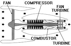
A high bypass turbofan engine.
A turbofan engine is basically a turbojet to which a fan has been added. Large fans can be placed at either the front or rear of the engine to create high bypass ratios for subsonic flight. In the case of a front fan, the fan is driven by a second turbine, located behind the primary turbine that drives the main compressor. The fan causes more air to flow around (bypass) the engine. This produces greater thrust and reduces specific fuel consumption.
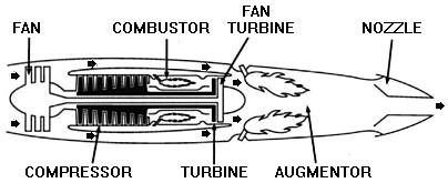
A low bypass turbofan engine.
For supersonic flight, a low bypass fan is utilized, and an augmentor is added for additional thrust.