Quantization error analysis of the quadrature components of narrowband signals
Размещено на /
QUANTIZATION ERROR ANALYSIS OF THE QUADRATURE COMPONENTS OF NARROWBAND SIGNALS
The implementation of filters with digital circuits having finite word-length introduces unavoidable quantization errors. These effects have been widely studied [1–7]. The three common sources of quantization error are: input quantization, coefficient quantization and quantization in arithmetic operations. In [2–4, 6] papers the statistical characteristics of the quantization errors of scalar signals have been studied. The influence of all three sources of quantization errors on performance of a Chebyshev digital third-order highpass filter was investigated in [5] also for the scalar input signals. The quantization errors of complex input signals, which were represented by its inphase and quadrature components were studied in [7] to evaluate the performance of coder/decoders with phase shift keying. However, only computer simulation results were presented in this paper.
Usually digital signal processing of
narrowband radio signals (i.e. signals for which inequality
 is valid) is carried out after the demodulation of the input signal
into the quadrature components. Hence, our attention in this paper
will be on input quantization of the complex signals. We adopt
stochastic methods to analyse quantization errors [1–6]. The
block diagram of the input narrowband signals converter, which
produces the quadrature components of the signals and then transforms
them into digital form is shown in fig. 1 (the left part of the
plot).
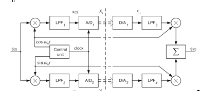
Fig. 1. Block diagram of narrowband signals' converter
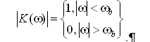
The converter contains two frequency mixtures, two low pass filters (LPF), two analog-to-digital converters (A/D) and a control unit. The quantizing (roundoff) errors of the inphase Xi and the quadrature Yi components are caused by limited bit representation of the code words of these components. To quantitatively evaluate these errors we will transform the quadrature components which have the roundoff errors into the narrowband signal again, and then we will estimate the amplitude and phase errors in this signal in comparison with the input one. For this purpose we will add in the block-diagram in fig. 1 the necessary blocks (the right part of the plot): digital-to-analogue converters (D/A), low pass filters (LPF) which restore the continuous analogue signal, frequency mixtures and adder. Assume all blocks work in ideal mode, don't introduce the delay, then the magnitude of the transfer function of the LPF is
If the Nyquist constraint is valid
the values of the restored analogue quadrature components
 and
 (
 is
the clock period) will be equal to the discrete values of quadrature
components –
 and
 respectively.
Preliminaries
Let
 and
 be the inphase and quadrature components at the input of the A/D
converters. At each sampling instant i, the quantized outputs
and
,
the quantization (roundoff) errors
 and
 ,
and the input
 and
 are related by
 ,
 .
(1)
Suppose
roundoff errors are independent with zero mean, variance
 and uniform distribution in interval
 ,
cf. [6].
 is
the step of quantizing.
If
the input signal is a narrowband signal
 ,
then
the output signal
 is
also a narrowband signal and can be written in the form
 (2)
where
the values of
and
are given by formula (1).
The
vector representation of the
 and
 signals is given in fig. 2. Obviously, we have
 .
(3)
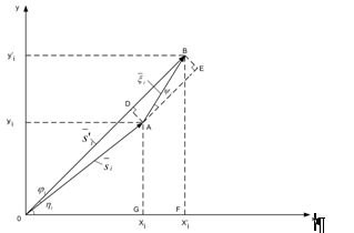
Fig. 2. Vector representation of input and output (distorted) signals
Under
the assumption about independent random variables
and
the hypothesis about uniform distribution of the random angles
 may be accepted. It is clear from the fig. 2 and formula (2) that the
signal
has
a parathytic amplitude modulation as well as a phase modulation. The
parathytic modulation is caused by the quantizing errors of the
signal's quadrature components.
Amplitude error analysis of the quantized narrowband signals.
The
variance of the magnitude
 is
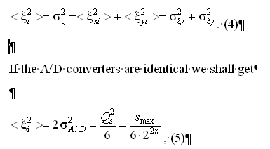
where smax is the maximum available amplitude of the input signals of the A/D converter, n – is the number of bits of the A/D converter.
It is interesting to note that
quantizing errors exist only when the input signals exists,
nevertheless these errors are additive but not multiplicative because
the values of these errors depend on the quantizing step
 ,
but do not depend on the amplitude of the input signal
.
(See formula (5)). We are interested in the amplitude and phase of
the output signal
 .
Let us find the statistical characteristics of the amplitude and
phase.
The length
 of the vector
 can easily be found from the triangle OAB (see fig. 2)
 ,
(6)
where
 .
As
the amplitude
 is the random variable, let us find the mean of this amplitude
 .(7)
Since
for many practical interesting cases
 ,
we shall use the decomposition
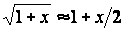 ,
hence
 .
(8)
Considering the formulas (4) and (5) we will find the mean of values in formula (8)
 ,
(9)
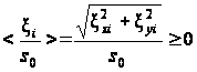 .
(10)
The
angle
 is (see fig. 2)
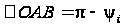 ,
hence
 ,
(11)
because
 is a random variable with uniform distribution in interval
 .
By
inserting the values given by formulas (9)–(11) into the
formula (8) we get the mean of the amplitude
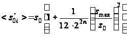 .(12)
Notice that the value of s0 in the formula (12) has to satisfy
 (12a)
as the amplitude of the input signal must exceed the quantization step.
Analysis
of formula (12) shows that if
 and if the number of bits of the A/D converter
 then the mean
 is equal to the
 with the error less than 0,5 %. This means that the mean amplitude of
output signal is practically equal to the amplitude of the input
signal.
The
variance of amplitude
can be found considering formula (6) and the fact, that


Supposing that
and using the decomposition
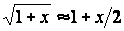 ,
the formula (13) can be written
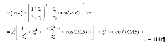
Where
 .
If we have identical A/D converters, then
 ,
(15)
Where
